Bmw 1 Series F20 Fuse Box Diagram
Fuses and relay BMW 1 2011-2018
For the BMW 1 series (F20, F21) 2011, 2012, 2013, 2014, 2015, 2016, 2017, 2018 model year.
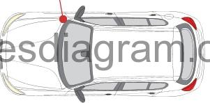
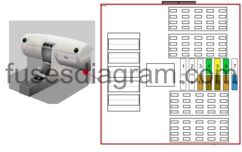
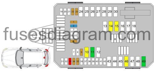
Fuse box in engine compartment.
fuse box location.
fuse box diagram.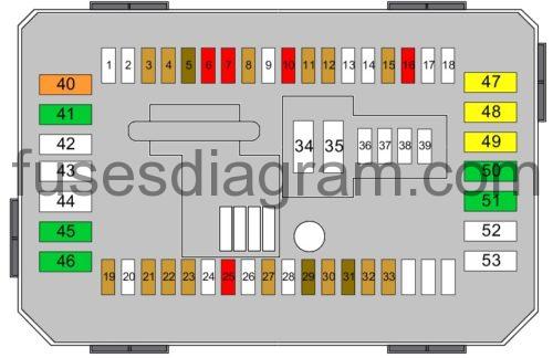
legend.
| Fuses | Amps | Circuits protected |
|---|---|---|
| 1 | Not used | |
| 2 | Not used | |
| 3 | 5A | Control unit, roof electronics |
| 4 | Not used | |
| 5 | 7.5A | Door lock switches Passenger's rear-view mirror |
| 6 | 10A | Engine control unit |
| 7 | 10A | Electronic automatic transmission (EAT) control unit |
| 8 | 5A | Touchbox Body control unit |
| 9 | Not used | |
| 10 | 10A | Seat adjustment |
| 11 | 5A | Front left vanity light Front right vanity light Rain sensor Interior lighting |
| 12 | 5A | Cut-off relay Dynamic stability control (DSC) |
| 13 | Not used | |
| 14 | Not used | |
| 15 | 5A | Transfer box |
| 16 | 10A | Coolant pump Air-conditioning compressor Additional water pump |
| 17 | Not used | |
| 18 | Not used | |
| 19 | 5A | Electrochromatic rear-view mirror |
| 20 | Not used | |
| 21 | 5A | Driver's assistance system |
| 22 | 5A | Cruise control |
| 23 | 5A | Crankcase breather heater Coolant shut-off valve |
| 24 | Not used | |
| 25 | 10A | Steering column switches |
| 26 | Not used | |
| 27 | 5A | Instrument cluster |
| 28 | Not used | |
| 29 | 7.5A | Instrument cluster |
| 30 | 5A | Glovebox illumination |
| 31 | 7.5A | Gear selector switch |
| 32 | 5A | Electronic power steering (EPS) |
| 33 | 5A | Air quality sensor |
| 34 | Not used | |
| 35 | Not used | |
| 36 | Not used | |
| 37 | Not used | |
| 38 | Not used | |
| 39 | Not used | |
| 40 | 40A | Fuse box |
| 41 | 30A | Dynamic stability control (DSC) |
| 42 | Not used | |
| 43 | Not used | |
| 44 | Not used | |
| 45 | 30A | Convertible roof |
| 46 | 30A | Transfer box |
| 47 | 20A | Heated passenger's seat |
| 48 | 20A | Heated driver's seat |
| 49 | 20A | Cigarette lighter |
| 50 | 30A | Driver's seat control unit Driver's seat adjustment |
| 51 | 30A | Passenger's seat adjustment Passenger's seat control unit |
| 52 | 12V supply | |
| 53 | Not used |
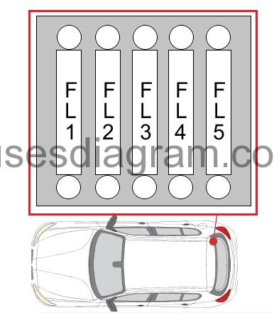
Fuse box in engine compartment (right side).
fuse box diagram.
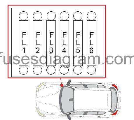
| Fuses | Amps | Circuits protected |
|---|---|---|
| FL1 | 50A | (80A also used) (125A also used) Cut-off relay |
| FL2 | 125A | Electronic power steering (EPS) |
| FL3 | 100A | Additional heater |
| FL4 | 40A | Heated fuel filter |
| FL5 | 40A | Dynamic stability control (DSC) |
| FL6 | 40A | Blower motor |
Fuse and relay box in engine compartment.
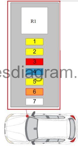
| Fuses | Amps | Circuits protected |
|---|---|---|
| 1 | 20A | Engine control unit |
| 2 | 20A | Engine control unit |
| 3 | 10A | Engine control unit |
| 4 | 15A | Engine control unit |
| 5 | 20A | Engine control unit |
| 6 | 40A | Engine control unit |
| 7 | 50A | Coolant pump |
| R1 | DDE main relay |
Additional fuses in passenger compartment.
| Fuses | Amps | Circuits protected |
|---|---|---|
| 1 | Not used | |
| 2 | Not used | |
| 3 | Not used | |
| 4 | 30A | Passenger's power window |
| 5 | 20A | Central locking |
| 6 | 30A | Driver's power window |
| 7 | Central locking | |
| 8 | Not used | |
| 9 | Not used | |
| 10 | 5A | Control panel Driver's assistance system Heating, ventilation and air conditioning (HVAC) Lights switch |
| 11 | 7.5A | Rear module Left headlight |
| 12 | 7.5A | Diagnostic socket |
| 13 | 5A | Telematics |
| 14 | 15A | Horn |
Fuse and relay box in luggage compartment.
fuse box diagram.
legend.
| Fuses | Amps | Circuits protected |
|---|---|---|
| 1 | 5A | Camera control unit |
| 2 | 15A | Radio control unit |
| 3 | Not used | |
| 4 | Not used | |
| 5 | Not used | |
| 6 | 5A | Sound system |
| 7 | Not used | |
| 8 | Not used | |
| 9 | 5A | Telematics |
| 10 | 20A | Radio control unit |
| 11 | 30A | Hi-Fi amplifier |
| 12 | Not used | |
| 13 | Not used | |
| 14 | 20A | Trailer towing module |
| 15 | 20A | Trailer towing module |
| 16 | Not used | |
| 17 | Not used | |
| 18 | Not used | |
| 19 | Not used | |
| 20 | Not used | |
| 21 | Not used | |
| 22 | 5A | Siren Microwave sensor |
| 23 | 5A | Remote control receiver Vacuum leak detection |
| 24 | Not used | |
| 25 | Not used | |
| 26 | Not used | |
| 27 | Not used | |
| 28 | Not used | |
| 29 | Not used | |
| 30 | Not used | |
| 31 | Not used | |
| 32 | Not used | |
| 33 | 10A | Sound system |
| 34 | 5A | DVD player |
| 35 | 5A | Base plates |
| 36 | Not used | |
| 37 | Not used | |
| 38 | Not used | |
| 39 | Not used | |
| 40 | Not used | |
| 41 | Not used | |
| 42 | Not used | |
| 43 | Not used | |
| 44 | Not used | |
| 45 | Not used | |
| 46 | 20A | Trailer socket |
| 47 | Not used | |
| 48 | Not used | |
| 49 | 30A | DC-DC converter |
Fuse box in luggage compartment.
| Fuses | Amps | Circuits protected |
|---|---|---|
| FL1 | 50A | Rear module |
| FL2 | 10A | Fuse box |
| FL3 | 10A | Power distribution |
| FL4 | 125A | Power distribution |
| FL5 | 125A | Integrated supply module |
Source: https://fusesdiagram.com/bmw/fuses-and-relay-bmw-1-2011-2018.html
Posted by: charitareynvaane0194603.blogspot.com

Post a Comment for "Bmw 1 Series F20 Fuse Box Diagram"